Determining Maximum Speeds and Accelerations
![]() This page is compatible with Klipper only.
This page is compatible with Klipper only.
Table of contents
This article is purely about finding your absolute maximum speeds/accels. This does not necessarily mean that these speeds or accelerations will be practical to print with, and in fact your max speeds/accels will often be way higher than is reasonable to daily drive (for longevity).
It’s very handy for troubleshooting motor skipping issues, and for optimizing 0.9° motors, however. You can also use these speeds for travels (but fast travels have significantly dimishing returns for overall print times). Or just if you’re into speed benchies.
It’s also just a bit of fun. haha printer go brrrr
Notes:
-
1.8° motors can generally reach higher top speeds/accels than 0.9° motors.
- For example my 2a 0.9° LDO motors top out around 450mm/s. My 2a 1.8° OMC motors could reach closer to 800-1000mm/s.
-
You may be able to get higher performance out of your motors by increasing currents (see
 here for more info), but be careful not to push them too high.
 -
You may also get higher maximum accelerations by utilizing input shaper, and may want to re-tune your max accels after tuning input shaper.
-
Higher voltage systems (e.g. 24v vs 12v) can also generally reach higher top speeds/accels.
Method
Tune maximum accelerations first, then tune speeds second.
The acceleration test does need reasonably fast speeds to ensure accuracy, however. Make sure that your max_velocity in your config is set to this reasonably fast speed that you already know works reliably.
There is some interplay between accelerations and speeds. You may get a slightly higher maximum speed with a slightly lower maximum acceleration and vice versa. Experiment!
- Add this macro to your
printer.cfgfile.- If your printer is a delta, use this version instead.
- If your printer is a delta, use
- Fully heat soak your printer if enclosed.
- Ideally the test should be run at the same chamber temps as your actual printing conditions.
- Run the
TEST_SPEEDmacro using the instructions below with increasing accelerations until you experience skipping.
 - Start with a small number of iterations.
- Example:
TEST_SPEED ACCEL=5000 ITERATIONS=2
- Example:
- Once you experience skipping, back the acceleration down and try again until you no longer get any skipping.
- Start with a small number of iterations.
-
Once you have found a rough maximum, run the test again with a large number of iterations.
- This is essentially an extended torture test.
- Example:
TEST_SPEED ACCEL=5000 ITERATIONS=50
- Example:
- If you experience any skipping during extended tests, back the speed down again.
- This is essentially an extended torture test.
- Save your new maximum acceleration to
max_accelin your config andRELOAD.-
Use a slightly lower value than your results.
- Often times, a maximum found through synthetic tests (even in extended tests) can skip during actual prints. Go a bit lower for a margin of safety. ~15% lower often works for me, but your mileage may vary.
-
Use a slightly lower value than your results.
-
Use the “acceleration” graphing calculator at the bottom of the page
here to find the theoretical maximum speed for your acceleration/print area. Remember it for the next step.-
This is only a theoretical maximum. I will explain more in the next step.
-
For example, for a 300mm printer*, with a max accel of 3500:
-
* Note that the test pattern is inset 20mm by default to help avoid collisions. Hence the distance of 260mm (300-20*2).
-
The “desired speed” field is mostly arbitrary for our purposes. Enter anything or use the default.
- This yellow line shows that we would theoretically max out a bit over 900mm/s at this acceleration/distance.
-
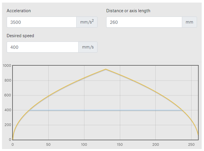
- The blue line just shows how far a given speed would be maintained (400mm/s in this example - arbitrarily chosen)
-
-
- Repeat the process (steps 1-6), this time increasing speeds rather than accelerations.
- Keep in mind that you can only go up to the theoretical maximum value you found in the previous step.
-
In most cases, this is very high and a non-issue.
-
In some cases, however, you may be wondering why you can achieve seemingly “infinite” speeds. This probably means that your printer is not actually able to reach the requested speed at that accel/distance!
-
- Once again, run an extended “torture test” once you find your rough limit.
- Example:
TEST_SPEED SPEED=450 ITERATIONS=50
- Keep in mind that you can only go up to the theoretical maximum value you found in the previous step.
- Save your new maximum speed to
max_velocityin your config andRELOAD.-
Use a slightly lower value than your results.
- Often times, a maximum found through synthetic tests (even in extended tests) can skip during actual prints. Go a bit lower for a margin of safety. ~15% lower often works for me, but your mileage may vary.
-
Use a slightly lower value than your results.

Usage of the TEST_SPEED Macro
The macro is available ![]() here.
here.
This macro will home, QGL*, move the toolhead in a test pattern at the specificed speeds/accels, and home again.
- *If your printer uses QGL / has not yet done a QGL. This is important, as a contorted gantry can cause alignment issues and skipping.
You will ![]() watch, listen, and compare the terminal output from before/after.
watch, listen, and compare the terminal output from before/after.
Available Arguments
(omitting any will use the default value)
-
SPEED- Speed in mm/sec.- Default: your
max_velocity
- Default: your
-
ACCEL- Acceleration in mm/sec².- Default: your
max_accel
- Default: your
-
ITERATIONS- Number of times to repeat the test pattern- Default: 5
-
BOUND- (Normally you do not need to specify/change this) How far to inset the “large” test pattern from the edges (in mm).This just helps prevent slamming the toolhead into the sides after small skips, and also accounts for imperfectly set printer dimensions.- Default: 20
-
SMALLPATTERNSIZE- (Normally you do not need to specify/change this) The box size of the small movement pattern to perform at the center (in mm).- Default: 20
![]() Note that the speeds/accels you input can override the
Note that the speeds/accels you input can override the max_velocity and max_accel in your config.
Examples
-
TEST_SPEED SPEED=400 ITERATIONS=50 -
TEST_SPEED ACCEL=10000 ITERATIONS=50
Determining if Skipping Occured
- Watch and listen.
- Often, the skipping will be very obvious. Your toolhead may start shuddering and making erratic movements and loud noises.
-
If there was no apparent major skipping, check for minor skipping:
- Inspect the g-code terminal output:
- Compare the numbers for the X and Y steppers for the first and second homing.
-
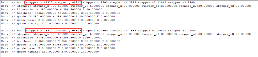
- These numbers represent the microstep position of the toolhead at X/Y max position.
-
Ensure that the difference between these numbers has not exceeded a full step.
-
For example, I am running
microstepsof 32 for my A and B motors. I would ensure that the values for each axis have not changed by more than 32. -
If the number has deviated more than this, that means that the corresponding axis has likely skipped.
-
Measuring to a full step just accounts for a bit of endstop inaccuracy. It does not necessarily mean that any microsteps were lost.
For hall effect endstops, you may need to measure to a few full steps. They can be bit less accurate, and they thermally drift.
-
- Inspect the g-code terminal output:
